Custom Welding Systems: Drawings and Information Required for Quotation
News Details
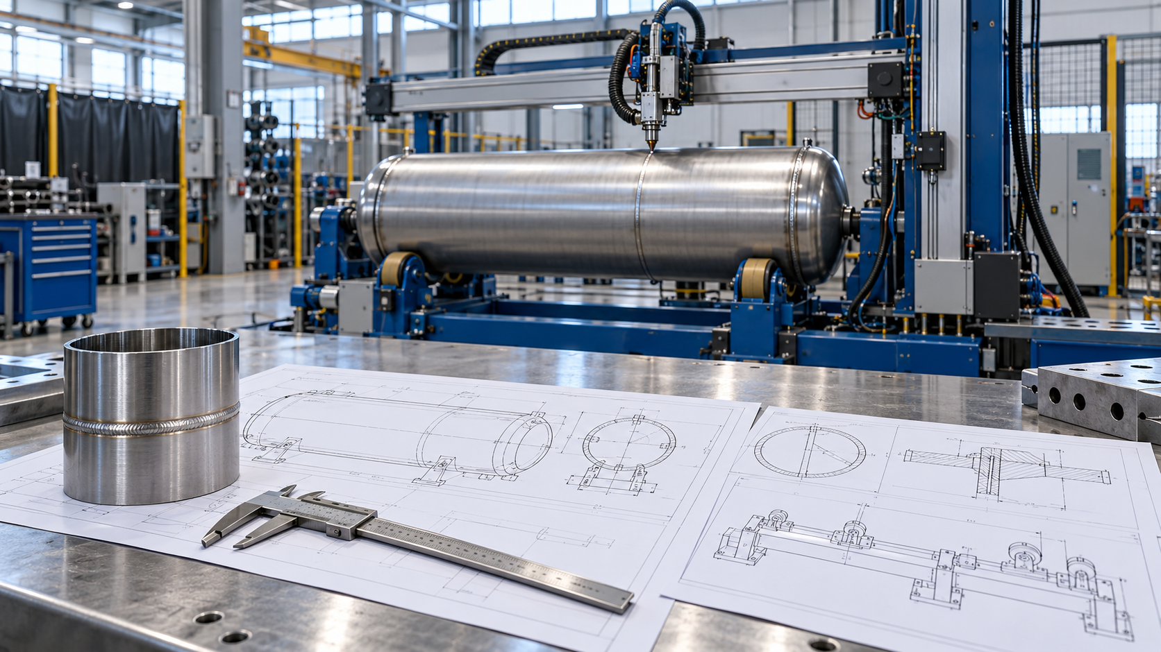
A custom welding system begins with a clear understanding of your parts and production requirements. Before a supplier can determine the appropriate welding process, fixtures, and motion controls, they must understand what exactly needs to be welded.
For buyers, providing a comprehensive request for quotation helps minimize guesswork. Additionally, it facilitates easier comparison among competing offers. This guide outlines which drawings and data should be prepared before reaching out to a custom welding machine manufacturer.
Why Customized Welding Systems Require Detailed Input
Welding automation demands precise control over the torch path, travel speed, heat input, and workpiece position. Simultaneously, the machine must adapt to the physical characteristics of the actual parts, accounting for minor variations in shape and fitting.
For instance, two vessels of the same diameter might require distinct systems due to differences in wall thickness, seam accessibility, or loading methods. Consequently, a mere photograph of a part rarely offers sufficient detail for providing an accurate quote.
Clear and comprehensive input enables suppliers to delineate both the equipment specifications and the limitations of their proposed solution.
Compile Part Drawings and Size Specifications
Initiate the process by providing dimensioned 2D drawings. Additionally, if available, include 3D models to clarify complex geometries, fixtures, and potential clearance constraints.
Incorporate the following:
- Overall length, width, height, or diameter.
- Wall thickness and material grade.
- Maximum permissible workpiece weight.
- Critical dimensional tolerances.
- Weld locations and corresponding joint cross-sections.
- Minimum and maximum dimensions within the product range.
Always annotate the drawing revision. Furthermore, specify whether the machine will be dedicated to a single part or accommodate multiple part families.
A system designed for a fixed part size may leverage simpler tooling. Conversely, a system addressing a broad size range might necessitate adjustable supports, extended travel capabilities, or interchangeable fixture sets.
Provide the Custom Welding Machine Manufacturer with Comprehensive Joint Specifications
The joint represents the interface where components are joined. Its geometry and fit significantly influence the welding process.
Clearly indicate whether each weld constitutes a butt joint, fillet weld, lap joint, or another type. Subsequently, include details such as groove angle, root gap, root face, and requisite weld dimensions, as applicable.
Additionally, clarify the following:
- Whether welding access is limited to one side or available from both sides.
- Whether backing is permissible or mandatory.
- The methods employed for part cutting, forming, and tack welding.
- Expected variations in joint gap and alignment.
- Whether internal tools or torches can be inserted into the part.
These specifications assist the supplier in evaluating clamping requirements and the potential utility of seam tracking technology. Automation ensures consistent execution of a controlled process, but it cannot compensate for suboptimal joint fit.
Communicate Material and Weld Quality Standards
Provide the precise material grade, rather than utilizing a generalized term such as "stainless steel." Include information regarding any coatings, oils, scale, or other surface conditions present prior to welding.
If a welding procedure specification is already in use, share it. Alternatively, describe the current process, filler wire, shielding gas, and any known welding challenges.
Subsequently, define the acceptance criteria for the completed weld. These requirements may encompass appearance, penetration depth, distortion, leak tightness, or mechanical strength. Specify any applicable industry codes, customer specifications, and inspection methodologies.
Should process trials be necessary, representative samples facilitate the validation of the proposed method. Samples should replicate typical production conditions, including realistic variations in part fit.
Equip Your Welding Automation Integrator with Concrete Output Targets
A welding automation integrator requires more than just a target welding speed; it necessitates knowledge of the desired output of the entire workstation.
Share your daily production volume, shift duration, batch size, and planned product mix. Additionally, specify the desired cycle time and the number of operators required to oversee the equipment.
Total cycle time encompasses:
- Loading and unloading operations.
- Positioning and clamping procedures.
- Welding and repositioning between seams.
- Any requisite cooling or cleaning steps.
- Part changeovers and fixture adjustments.
Consequently, even an accelerated torch travel speed may fail to deliver the anticipated output if loading procedures remain inefficient. Request the supplier to articulate the underlying assumptions informing their cycle time estimate.
Provide Facility Layout and Utility Specifications
Submit a concise floor plan delineating the available space, access routes, neighboring machinery, and designated loading area.
Furthermore, confirm the availability of electrical power, compressed air, shielding gas, cooling water (if required), and fume extraction infrastructure. For large-scale components, describe the crane, forklift, or alternative lifting apparatus.
Additionally, outline the workflow for introducing and removing parts from the station. If the proposed system must integrate with pre-existing equipment, specify the required control signals and data interfaces.
This information aids in delineating the scope of installation prior to finalizing cost projections.
Align Juchuang Equipment with Your Welding Objectives
Juchuang's product portfolio encompasses welding manipulators, plate butt and longitudinal seam welding machines, side beam systems, and twin-torch half-pipe welding systems. These offerings address diverse seam geometries and workpiece handling requirements.
For instance, a straight seam mandates distinct motion parameters compared to a circumferential or helical seam. Therefore, clearly delineate each weld path and specify whether the workpiece is rotatable. This provides Juchuang with a practical foundation for evaluating and designing a custom welding system.
Initiate a Request for Quotation with a Well-Defined Scope
Prior to dispatching your inquiry, consolidate all pertinent documentation, including drawings, material specifications, weld standards, output targets, and site data, into a comprehensive package.
Subsequently, request the supplier to itemize the included equipment, tooling, trial procedures, installation services, training programs, spare parts provisions, and explicitly excluded items. Additionally, agree upon the acceptance testing protocols and representative workpieces.
To initiate discussions regarding your project, please contact Juchuang with your available drawings and production requirements. Should certain details remain unresolved, clearly label them to ensure the quotation accurately reflects its underlying assumptions.


